

Research on the Impact of Different Designs of Twin-Screw Extruder Screw Elements on the Mixing Effect of High-Viscosity Polymers
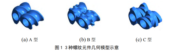
This article uses finite element software to study the flow field characteristics of high-viscosity polymers in three types of threaded components: conventional threaded components, slotted threaded components, and meshing blocks. It analyzes the impact of different fluid parameters on the mixing performance of the three types of threaded components.
In order to facilitate calculations, the simulated working conditions are simplified as follows:
1) The density of the polymer melt remains unchanged during the mixing process.
2) Ignore the turbulent flow of the melt and consider only laminar flow.
3) Ignore body forces such as gravity and inertial forces;
The melt is in a completely filled state in the runner.
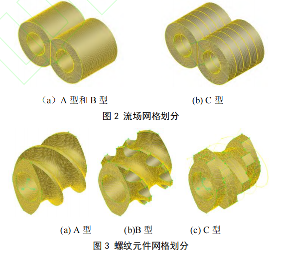
Finite element model: Use preprocessing software to mesh the flow field and threaded components separately, as shown in Figures 2 and 3.
Boundary conditions for the aggregated flow field: both the inlet and outlet of the flow field are in a natural flow state (fn=fs=0), the screw rotation speed on both sides is 300 r/min, and there is no relative motion on the inner surface of the barrel.
01. Pressure in the flow field of threaded components
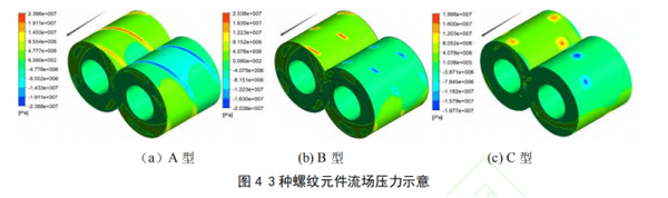
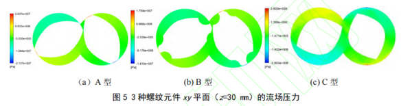
From Figure 4, it can be seen that:
In the direction of rotation of the twin-screw extruder, the pressure near the exit side of the flow field is higher, with the highest pressure in the area where the screw elements mesh. Since the polymer is a non-Newtonian power-law fluid, the melt pressure suddenly increases as the screw flights advance, and gradually decreases after leaving the screw flights. The overall trend is that the pressure gradually increases from the inlet to the outlet. This is because during the extrusion process, the melt experiences a significant driving force at the screw flights, and while the extrusion pressure decreases after leaving the screw flights, the flow field pressure gradually increases as the melt continues to mix and compact.
In addition, the outlet pressure of the flow fields for the three threaded components is greater than the inlet pressure, and the pressure gradient changes significantly, indicating that all three threaded components have the ability to build pressure. Type B has eight evenly distributed helical grooves on its outer wall, which leads to significant leakage and mixing phenomena of the material as it passes through the internal cavity. Therefore, the pressure field of Type B changes less, while the velocity field changes more, and the local shear rate changes less.
Peak pressure of the flow field: Type A > Type B > Type C.
02. Local shear rate of threaded components
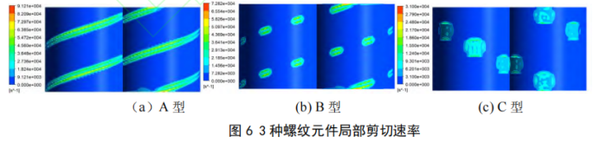
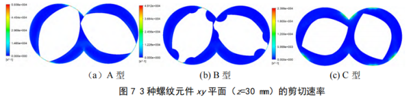
From Figures 6 and 7, it can be seen that:
The high shear stress is mainly concentrated in the meshing area of the two threaded components and between the threaded components and the inner wall of the cylinder.
Along the extrusion direction, the peak local shear rate of Type A is the highest, followed by Type B, and Type C is the lowest.
03. Melt velocity of threaded component plane
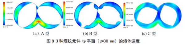
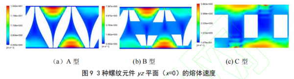
From Figures 8 and 9, it can be seen that:
The speed of the three types of threaded components is relatively high near the screw edge, and the melt speed in the meshing area will suddenly increase. In the vicinity of the center of the barrel, there is a significant backflow of the melt, which is beneficial for the full mixing of the melt.
Melt flow performance: Type A > Type B > Type C.
04. The Influence of Rheological Parameters on Mixing Performance
Select a typical A-type model and analyze the impact of different rheological parameters on the mixing performance. Figure 10 shows the sampling points of the A-type model, where the arrows indicate the extrusion direction, and points A and B are the sampling points. Figure 11 presents the parameter analysis for the A-type model.
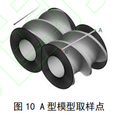
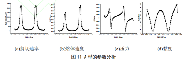
Figure 11(a) shows that the local shear rate varies continuously with the position of the helical ridge and the supporting surface of the helical ridge. It increases sharply near the helical ridge, while the local shear rate is minimal at the inlet and outlet of the entire flow field region. The local shear rate at the first supporting surface of the helical ridge exceeds 2,750 s⁻¹, and the local shear rate at the groove position (axial position of 3 cm) is minimal, approaching 0.
From Figure 11(b), it can be seen that when the screw conveys the material to the inlet side, the melt speed is relatively low. As the mixing progresses, the melt speed gradually increases, exceeding 0.12 m/s at the first screw ridge (z=0.015 m). After passing the first screw ridge, it quickly drops again. This is because the material is continuously conveyed forward in a spiral manner within the twin-screw extruder, and the material is subjected to friction between the two screws, causing the melt speed to decrease rapidly. When it approaches 0, it essentially stabilizes. When the material reaches the second screw ridge (z=0.05 m), the melt speed rapidly rises to 0.17 m/s, then quickly decreases again and tends to stabilize.
As shown in Figure 11(c), the pressure variation characteristics during the extrusion process have been described. The trend of pressure changes is similar to that of local shear rate and melt flow rate, indicating that the three are positively correlated; that is, when the pressure increases, both the shear rate and melt flow rate also tend to increase.
Shear stress increases with the increase of shear rate, while viscosity is inversely proportional to the former two. As shown in Figure 11(d), the trend of shear rate changes is opposite to that of viscosity changes. When the shear rate decreases, the viscosity distribution shows an increasing trend, and vice versa.
Experimental verification
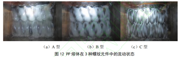
Figure 12 shows the flow state of PP melt in three types of screw elements, with the screw speed set at 300 r/min. As can be seen from Figure 12, the PP melt achieves a steady flow in all three screw elements, and there are basically no large clumps of material adhering to the inner wall of the cylinder or the screw elements, indicating that all three types of screw elements have good self-cleaning performance, demonstrating good mixing and shearing effects. Type A has the best shearing ability, followed by Type B, and Type C has the weakest.
In the early stages of the experiment, the designed screw combination only included threaded components and engaging blocks. However, the mixing performance of the entire reaction was relatively good, and the filling degree of the melt inside the barrel was high, but the back-mixing ability was weak.
Later, through simulation analysis, the position of the threaded components was adjusted by adding a slotted threaded component on the side of the engagement block closer to the feeding end, which improved the back-mixing capability of the entire flow field.
At the same time, the pressure-building capacity and conveying capacity of the grooved threaded elements are weak, resulting in a high degree of filling in the internal flow field, which can prolong the residence time. The experimental verification results are highly consistent with the simulation results. In addition, the length-to-diameter ratio of the screw has been reduced from 52:1 to 44:1.
【Copyright and Disclaimer】The above information is collected and organized by PlastMatch. The copyright belongs to the original author. This article is reprinted for the purpose of providing more information, and it does not imply that PlastMatch endorses the views expressed in the article or guarantees its accuracy. If there are any errors in the source attribution or if your legitimate rights have been infringed, please contact us, and we will promptly correct or remove the content. If other media, websites, or individuals use the aforementioned content, they must clearly indicate the original source and origin of the work and assume legal responsibility on their own.
Most Popular
-

Amcor Opens Advanced Coating Facility for Healthcare Packaging in Malaysia
-

ExxonMobil and Malpack Develop High-Performance Stretch Film with Signature Polymers
-

Plastic Pipe Maker Joins Lawsuit Challenging Trump Tariffs
-

Pont, Blue Ocean Closures make biobased closures work
-

Over 300 Employees Laid Off! Is Meina Unable to Cope?