


South China University of Technology: Pressure Drop Characteristics of Countercurrent Microfine Channels under the Synergistic Effect of Electric Field and Phase Separation Structure of Modified PVDF Membranes
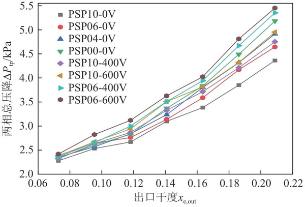
To address the issues of uneven flow rates, pressure drop fluctuations, and local overheating caused by the rapid expansion of volume due to phase change during the heat transfer process of two-phase flow in microchannels, this study investigates the pressure drop of flow boiling in countercurrent microchannels with different phase separation pore densities (PSP00, PSP04, PSP06, PSP10) under the influence of an electric field. A performance evaluation criterion (PEC) is introduced to study the comprehensive heat transfer performance of countercurrent microchannels with and without phase separation structures under different voltages (0, 200V, 400V, 600V). High-speed photography is utilized for visual study of the channels, and the variation rate of the aspect ratio of confined bubbles is introduced to analyze the growth behavior of confined bubbles within the channels. The research results indicate that as the pore density of the phase separation structure increases, the flow resistance and pressure drop within the channel decrease. With the increase of heat flux density, the reduction in two-phase pressure drop becomes more significant. The application of an electric field increases the two-phase pressure drop within the channel; however, the increase is less pronounced compared to the two-phase pressure drop in the channel after synergistic action with the phase separation structure. The two-phase pressure drop in the PSP10 channel with a phase separation structure under 600V is reduced by 14.2% compared to the PSP00 channel without a phase separation structure. Both the electric field and the phase separation structure can reduce the aspect ratio of confined bubbles in the microchannel, and the greater the pore density of the phase separation structure and the voltage, the smaller the aspect ratio of the confined bubbles. The combined effects of the electric field, phase separation structure, and their interaction all contribute to improving the overall heat transfer performance PEC of the microchannel. The best effect is achieved when both the electric field and phase separation structure are applied together, with larger pore density and voltage leading to a higher PEC. The maximum PEC when both the electric field and phase separation structure are simultaneously applied (PSP10-600V) is 1.30, which is an increase of 13.0% compared to the maximum PEC under the electric field alone (PSP00-600V) and an increase of 7.4% compared to the maximum PEC under the phase separation structure alone (PSP10).
Currently, methods to improve the phase change heat transfer efficiency in microchannels with two-phase flow include active, passive, and composite methods. Active enhancement techniques refer to the addition of external energy to enhance heat transfer (such as surface vibrations, electrodynamics, and magnetohydrodynamics). Passive enhancement techniques involve the use of additives (nanoparticles) in the working fluid, altering the properties of the heat transfer surface, or incorporating microstructures for enhanced heat transfer on the heat transfer surface. Composite enhancement techniques refer to the combined use of active and passive enhancement techniques. In passive enhancement techniques, hydrophobic porous membranes and capillary action from different microchannel structures are often used to achieve gas-liquid phase separation, addressing the issue of uneven gas-liquid distribution within microchannels. Studies by Priy et al. and Apreotesi et al. have shown that hydrophobic porous materials can effectively reduce pressure drops within microchannels. Luo Xiaoping et al. used a 30% glycerol aqueous solution as the working fluid and analyzed the pressure drop variations in two phase separation structures (porous/non-porous) and ordinary microchannels without exhaust holes. The results indicated that phase separation structures can significantly reduce the two-phase flow resistance within the channel, and that the ability to mitigate pressure drop increases with greater heat flux density and more open pores in the phase separation structure. In active enhancement techniques, external forces such as acoustic fields and electric fields are often applied to the microchannels to alter the heat transfer efficiency of the two-phase flow.
Tang et al. studied the effect of needle-shaped electrodes on the evaporation heat transfer of working fluids in heat pipes and microchannels. They found that the application of needle-shaped electrodes can promote an increase in capillary wetting length, reduce the wall temperature of microchannels, and effectively enhance heat transfer performance. Li et al. adopted a counterflow stepped microchannel to address the main issues faced by two-phase flow boiling in microchannels. Jing et al. used a counterflow diverging microchannel and found that compared to traditional co-flow designs, it significantly improved temperature uniformity, with a heat transfer coefficient increase of 45.1%, a pressure drop reduction of 73.8%, and a performance coefficient increase of 123.1%. From these studies, it can be observed that gas-liquid two-phase flow in direct contact with a liquid-repellent porous membrane or capillary structure can achieve a certain degree of separation between gas and liquid phases, effectively reducing local gas phase content, resulting in a more uniform working fluid within the channel, more stable heat transfer performance, and reduced pressure drop. However, the other side of such phase separation structures is in direct contact with the external environment, and during the phase separation process, there may be a certain degree of working fluid loss. Additionally, if the pressure within the channel becomes too high, the capillary structure or porous membrane may be damaged, posing safety hazards. The electric field applies a force to the gas-liquid interface, affecting the motion characteristics and morphology of bubbles, particularly having a significant impact on the growth and detachment processes of bubbles. However, the electric field mainly exerts a strong enhancement effect during the nucleate boiling stage, and as the heat flux density continues to increase, leading to a large number of confined bubbles in the channel, the enhancement effect of the electric field gradually diminishes. In terms of microchannel structure, counterflow microchannels can reduce the overheating region near the downstream outlet by facilitating heat exchange between hot and cold fluids, thereby improving the overall heat transfer performance of microchannels and enhancing temperature uniformity and pressure drop stability.
To address the aforementioned issues, this paper proposes a parallel counterflow microchannel structure, which features a gas-liquid phase separation structure with modified polyvinylidene fluoride (PVDF) porous membranes at its ribs. Additionally, needle-shaped electrodes are integrated into the phase separation structure, allowing for the synergistic effects of electric fields and phase separation to further enhance flow boiling heat transfer performance. The study investigates the two-phase pressure drop and bubble behavior in counterflow microchannels (PSP00, PSP10, PSP06, PSP04) with varying densities of gas-permeable pores under the absence of an electric field. Furthermore, the research visualizes the two-phase pressure drop and bubble behavior under different voltages (0, 200V, 400V, 600V) when the electric field (needle-shaped electrodes) collaborates with the modified PVDF membrane phase separation structure. Performance evaluation criteria (PEC) are introduced to examine the uniformity of surface temperature distribution and comprehensive heat transfer performance of PSP10 under no electric field and PSP00 and PSP10 under a voltage of 600V, providing references for the study of enhanced heat transfer in microchannels.
01
Experimental System and Experimental Plan
1.1
1.1.1 Preparation of Phase-Separated Porous Membranes and Selection of Working Fluids
The principle of gas-liquid separation using a porous hydrophobic membrane is based on a wetting behavior that occurs at the solid-gas-liquid interface. By utilizing the pressure difference across the porous hydrophobic membrane, some gas can be separated from the flowing gas-liquid two-phase mixture. Wetting refers to the process where one fluid replaces another fluid that was originally present on the solid surface when they come into contact. The wettability is primarily determined by the microscopic morphology and chemical composition of the solid surface, typically represented by the contact angle θ. The contact angle is defined as the angle formed between the tangent to the gas-liquid interface and the tangent to the solid-liquid interface at the three-phase contact point. In 1805, Young proposed Young's equation as shown in Equation (1).
In the formula, γsv is the surface tension of the gas-solid interface, N/m; γsl is the surface tension of the liquid-solid interface, N/m; γlv is the surface tension of the gas-liquid interface, N/m.
When θ < 90°, the solid surface exhibits wettability; when 90° ≤ θ ≤ 150°, the solid surface is considered non-wettable; when θ > 150°, the solid surface is superhydrophobic and non-wettable.
Currently, the commonly used porous hydrophobic membranes for microchannel phase separation include polytetrafluoroethylene (PTFE), polypropylene (PP), and polyvinylidene fluoride (PVDF). Among them, the porous membrane made of PVDF has excellent hydrophobicity and stability, allowing for long-term use at temperatures up to 120°C, and it is easy to process and shape. Therefore, this paper selects PVDF porous membranes to achieve gas-liquid phase separation. To enhance the hydrophobicity of the PVDF membrane, this paper employs a method used by Wu et al., utilizing a solution of 1H,1H,2H,2H-perfluorodecyltrichlorosilane (FDTS) to immerse and modify the PVDF membrane, followed by standing for 48 hours and then drying, resulting in the modified PVDF membrane. The contact angles of three commonly used working fluids (water, mineral oil, and ethanol) on the modified PVDF membrane were measured using a contact angle goniometer. It was found that the contact angle for water was 152°, for mineral oil 117°, and for ethanol 105°. The contact angles for all three working fluids were greater than 90°, with water having the largest contact angle and ethanol the smallest. Among them, the conductivity of ethanol solution is weak, allowing its liquid phase not to pass through the membrane, while the gas phase can pass through the membrane, and an electric field can be applied to it. Therefore, this paper uses industrial ethanol as the experimental working fluid.
1.1.2 Reverse Flow Structure Layout Plan
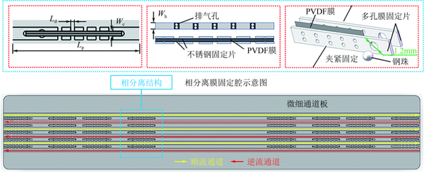
Figure 1
Reverse flow structure schematic diagram
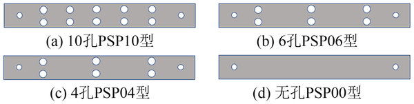
Figure 2
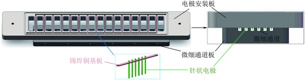
In order to ensure that the electric field in the channel can fully cover the microchannel, multiple rows of needle-like electrodes were set up. The needle-like electrodes are made from 304 stainless steel needles, with a diameter of 0.3mm and a length of 11mm. A direct current of 24V is applied to the needle-like electrodes, and the installation situation of the needle-like electrodes is shown in Figure 3. The back of the mounting plate makes contact with the microchannel plate, and the through holes on the mounting plate have a diameter of 0.5mm. The needle-like electrodes protrude 1mm from the back of the mounting plate, with the protruding parts located within the microchannel.
1.2
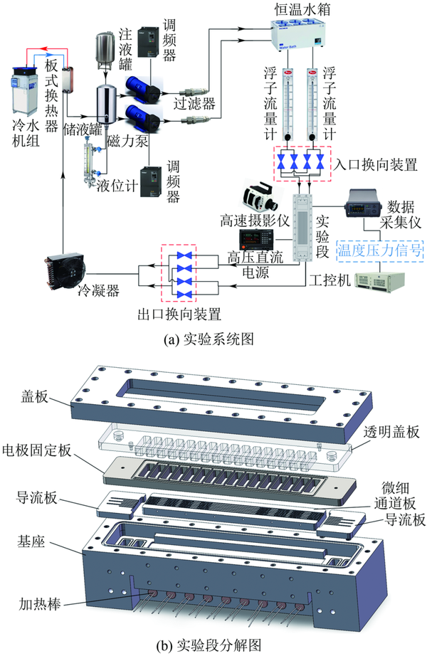
The experimental system is divided into five main parts: the liquid injection system, the preheating system, the experimental section, the cooling system, and the data acquisition system. First, the ethanol working fluid is injected into the storage tank through the liquid injection system. During the formal experiment, the magnetic pump pumps the working fluid into the preheating water tank, which is set to a predetermined temperature. After being preheated in the serpentine pipe within the preheating water tank, the working fluid is heated to a certain temperature before entering the experimental section. In the experimental section, the working fluid undergoes boiling due to the heating from the electric heating rod while flowing. After flowing out of the experimental section, the working fluid passes through the cooling system, where it is cooled by the heat exchanger before returning to the storage tank, forming a circulation. The diagram of the experimental system is shown in Figure 4(a).
02
2.1
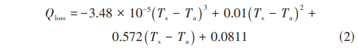
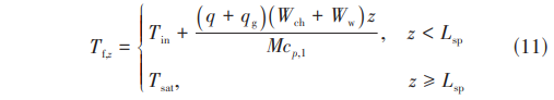
In the formula, Qloss is the heat loss power, W; Ta is the ambient temperature, °C; Ts is the average wall temperature, °C.

2.2

In the formula, G is the mass flow rate of the microchannel, kg/s; V is the volumetric flow rate, L/h; Nch is the number of channels in the same direction on the microchannel plate; Wch is the width of the microchannel, m; Hch is the height of the microchannel, m; ρl is the density of the working fluid ethanol, kg/m³.
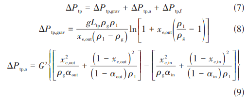
2.3

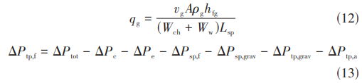
The calculation method for ΔPsp is shown in equation (6).


2.4

The method for calculating the relative uncertainty of R is shown in equation (16).
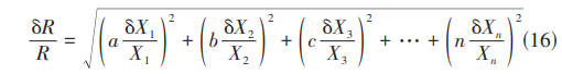
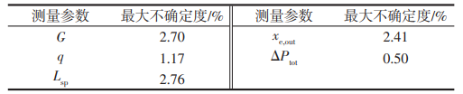
Table 1 Major Parameter Uncertainty
03
3.1
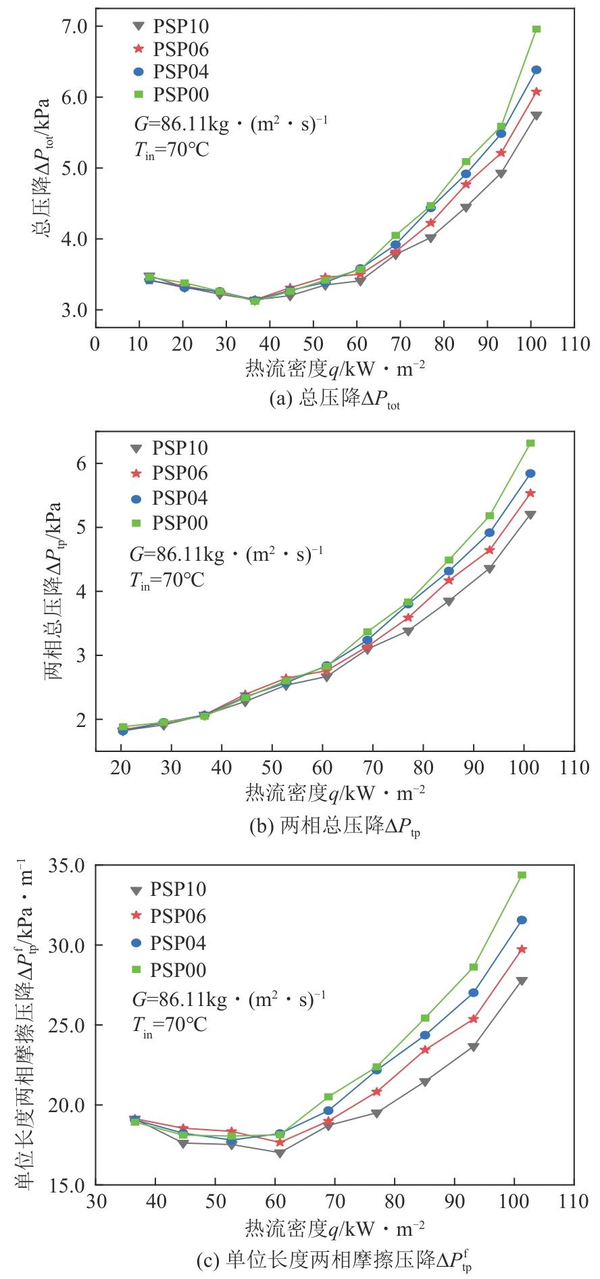
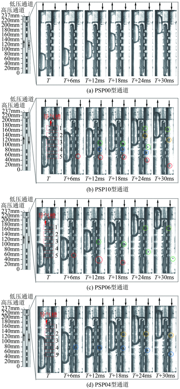
The effect of different phase separation pore densities on pressure drop in microchannels.
3.2
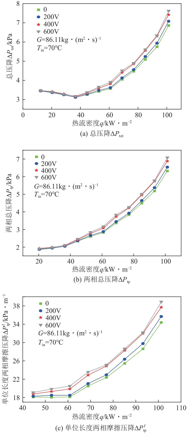

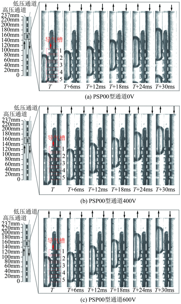
The variation trend of voltage drop characteristics of PSP10 channel under different voltage effects.
3.3
3.4

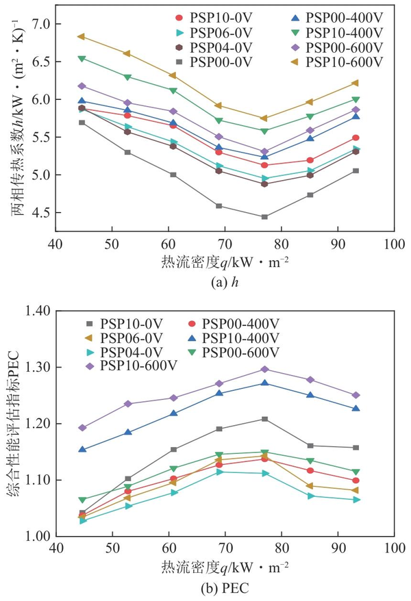
The phase separation structure with different pore densities and the variation of channel h and PEC with heat flow density under different voltage conditions.
04
【Copyright and Disclaimer】The above information is collected and organized by PlastMatch. The copyright belongs to the original author. This article is reprinted for the purpose of providing more information, and it does not imply that PlastMatch endorses the views expressed in the article or guarantees its accuracy. If there are any errors in the source attribution or if your legitimate rights have been infringed, please contact us, and we will promptly correct or remove the content. If other media, websites, or individuals use the aforementioned content, they must clearly indicate the original source and origin of the work and assume legal responsibility on their own.
Most Popular
-
Overseas Highlights: PPG Establishes New Aerospace Coatings Plant in the US, Yizumi Turkey Company Officially Opens! Pepsi Adjusts Plastic Packaging Goals
-
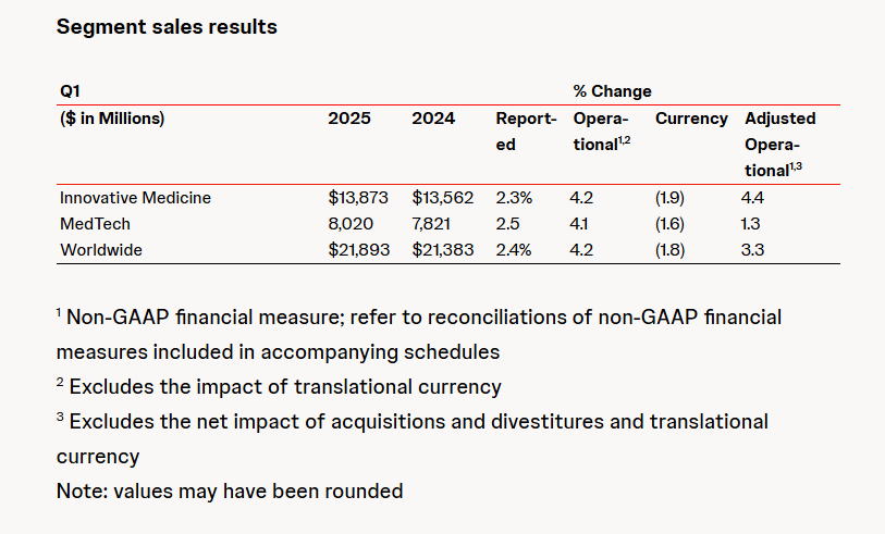
Abbott and Johnson & Johnson: Global Medical Device Giants' Robust Performance and Strategies Amid Tariff Pressures
-

BYD releases 2024 ESG report: Paid taxes of 51 billion yuan, higher than its net profit for the year.
-

Behind pop mart's surging performance: The Plastics Industry Embraces a Revolution of High-End and Green Transformation
-

The price difference between recycled and virgin PET has led brands to be cautious in their procurement, even settling for the minimum requirements.